wiretight lookup B002
B002 board set
You scanned a WireTight B002 board. Here's what it fits, how each board is wired, and how to install it.
Fits
| Unit | Arduino SKU | B002 |
|---|---|---|
| Arduino® Opta™ Ext D1608E (electromechanical relays) | AFX00005 | compatible |
| Arduino® Opta™ Ext D1608S (solid-state relays) | AFX00006 | compatible |
The Arduino SKU is printed on your module's label. The Opta base unit (AFX00001, AFX00002, AFX00003) uses B001; the A0602 analog expansion uses B003.
3D view
The B002 set seated on an Arduino® Opta™ Ext D1608E, shown with Micro-Fit headers. Drag to rotate, scroll or pinch to zoom. Pick a board to see it on its own, or lift the boards off the terminals.
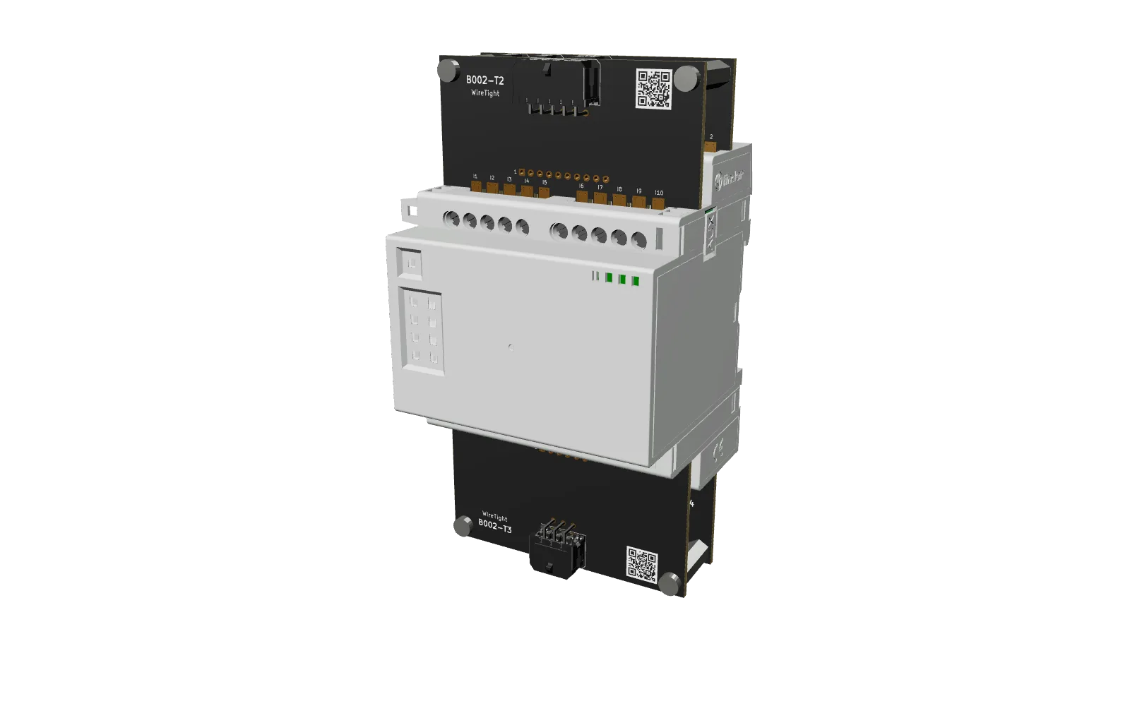
loading 3D model… (5 MB)
Module 3D model © Arduino S.r.l., from docs.arduino.cc, licensed CC BY-SA 4.0; converted to glTF, simplified and combined with WireTight board models. This 3D model and its renders are shared under the same license.
Four boards, two stacks
The expansion module has two terminal rows on top and two on the bottom. Boards are numbered from the top down.
| Board | Terminal row | Covers | Micro-Fit header |
|---|---|---|---|
| T1 | Top, back | + + − −, relays 1–2 | 2× 2×1 (power) + 2×2 |
| T2 | Top, front | Inputs I1–I10 | 2×5 |
| T3 | Bottom, front | Inputs I11–I16 | 2×3 |
| T4 | Bottom, back | Relays 3–8 | 1×12 |
T2 bolts to T1 and T3 bolts to T4 through the two corner holes, using M3 standoffs (included in the Full Kit). The bare kit has a row of plated 2.54 mm (0.1″) holes instead of a header. Hole 1 is marked on the board. Any 2.54 mm connector fits.
T1 · top back board
Supply and relays 1–2. 8 positions. Two identical 2×1 power headers: one for the supply in, one to pass it on. Relays: DC loads only, up to 5 A per channel (D1608E) or 3 A (D1608S).
| Module terminal | Signal | Bare hole | Micro-Fit pin |
|---|---|---|---|
| + | Supply + (12–24 V DC) | 1 | Power, pin 1 |
| + | Supply + (12–24 V DC) | 2 | Power, pin 1 |
| − | GND | 3 | Power, pin 2 |
| − | GND | 4 | Power, pin 2 |
| Relay 1 | Output 1, contact A | 5 | Relay 2×2, pin 1 |
| Relay 1 | Output 1, contact B | 6 | Relay 2×2, pin 2 |
| Relay 2 | Output 2, contact A | 7 | Relay 2×2, pin 3 |
| Relay 2 | Output 2, contact B | 8 | Relay 2×2, pin 4 |
On each power header, pin 1 (+) is the row away from the module and pin 2 (−) is the row nearest it. Feed it from the module to the left with the power jumper (included in the Full Kit), and pass power on from the other header.
T2 · top front board
Inputs I1–I10. 10 positions. Stacks on T1.
| Module terminal | Signal | Bare hole | Micro-Fit pin |
|---|---|---|---|
| I1 | Input 1 | 1 | 1 |
| I2 | Input 2 | 2 | 2 |
| I3 | Input 3 | 3 | 3 |
| I4 | Input 4 | 4 | 4 |
| I5 | Input 5 | 5 | 5 |
| I6 | Input 6 | 6 | 6 |
| I7 | Input 7 | 7 | 7 |
| I8 | Input 8 | 8 | 8 |
| I9 | Input 9 | 9 | 9 |
| I10 | Input 10 | 10 | 10 |
T3 · bottom front board
Inputs I11–I16. 6 positions. Stacks on T4. The header is mounted the other way up, so pin 1 is I16.
| Module terminal | Signal | Bare hole | Micro-Fit pin |
|---|---|---|---|
| I11 | Input 11 | 1 | 6 |
| I12 | Input 12 | 2 | 5 |
| I13 | Input 13 | 3 | 4 |
| I14 | Input 14 | 4 | 3 |
| I15 | Input 15 | 5 | 2 |
| I16 | Input 16 | 6 | 1 |
T4 · bottom back board
Relays 3–8. 12 positions on a single-row header. Pin 1 is relay 8, contact B. DC loads only, up to 5 A per channel (D1608E) or 3 A (D1608S).
| Module terminal | Signal | Bare hole | Micro-Fit pin |
|---|---|---|---|
| Relay 3 | Output 3, contact A | 1 | 12 |
| Relay 3 | Output 3, contact B | 2 | 11 |
| Relay 4 | Output 4, contact A | 3 | 10 |
| Relay 4 | Output 4, contact B | 4 | 9 |
| Relay 5 | Output 5, contact A | 5 | 8 |
| Relay 5 | Output 5, contact B | 6 | 7 |
| Relay 6 | Output 6, contact A | 7 | 6 |
| Relay 6 | Output 6, contact B | 8 | 5 |
| Relay 7 | Output 7, contact A | 9 | 4 |
| Relay 7 | Output 7, contact B | 10 | 3 |
| Relay 8 | Output 8, contact A | 11 | 2 |
| Relay 8 | Output 8, contact B | 12 | 1 |
On the D1608S, the two terminals of each output are marked + and −. Check the module label for polarity.
Install
- Power down the module, the Opta it's attached to, and everything they switch.
- Seat the back boards first. Put T1 on the top back row and T4 on the bottom back row, tighten each terminal, then screw two standoffs onto each.
- Add the front boards. Seat T2 and T3 on the front rows, screw them to the standoffs, and tighten each terminal. Check the pinouts above before plugging in and powering up.
Get the kit
Each B002 kit covers every board: bare, with Micro-Fit headers, or the full kit with standoffs. Ask about volume pricing and pre-built harnesses.
Shop B002 kits